top of page
Search

How I replaced my Atwood Levelegs Control Pad and Controller for CHEAP!

  • Writer: Nate
    Nate
  • 6 days ago
  • 7 min read

Background

In April 2024, we'd had our Tiffin Allegro Bay about 4 months, and the leveling jacks hadn't worked since we got it home. They worked when I picked it up in Polk City, but after an 800 mile journey, including over some very sketchy state roads (I'm looking at you Florida), the control pad was dead, and no amount of troubleshooting, even with the installation guide and manual in hand, could isolate the problem. Everything had power, and all of the various lockout sensors tested out, it was just dead. So, I explored the options - replace everything with a Bigfoot system or similar (way too expensive at $3k+), send it out for repair (expensive at ~$400 and no guarantees it wouldn't fail again), or go some other route. I went with plan "C".


The Plan

Initially, after much procrastination, I sat down and spec'd out a custom controller, using 100A continuous duty winch solenoids and a custom switch panel, that would use the existing jacks and wiring. I'd built something similar, albeit lighter duty, for a lighting setup on my SUV, and I've done lot's of 12v work on trucks, cars and ATVs over the years, so I'm pretty comfortable with "electrics". By the time I had identified all the components, my cost, before building it was around $400 all-in. Not bad, and I thought it would be something I could troubleshoot and repair easily, if it had any issues. However, while doing a little more research, I came across the GAMA Electronics RF340-4PR-ASL, which did everything I was trying to do, and more, and a good bit cheaper at that. Needless to say, I ditched my plans, as fun as they would have been, got the RF340-4PR-ASL and the HP4PR-ASL handheld pendant controller, and all for around $235 shipped.


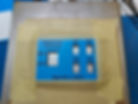
Never one to leave anything "stock", I decided to replace the handheld pendant with a custom switch panel, designed to mount in the same location on the dash as the Atwood control pad, use the cable from the GAMA pendant to connect to the GAMA control board, in the same location as the Atwood controller. I designed and 3D printed a custom switch panel, as well as an adapter plate so I could use the old brackets from the Atwood system.


Let's say "goodbye" to this garbage, forever!
Hello GAMA RF340-4PR-ASL!

Switch Panel and Adapter Design and Manufacture

The switch panel is a simple design, and originally was supposed to have 3-dimensional labels as part of the print, but on my first test print with PETG, due to the stringing that is common with that material, I had to abandon that plan and go with a stencil and paint for the labels.


Switch panel and stencil in 3D.
Switch panel with stencil, ready for paint. Stencil created using my daughter's Cricut machine and some stencil vinyl. The dots for the a's and o's were fun!
Switch panel, painted and switches installed. I primed with Krylon Fusion, and then top coated with Ace Premium Enamel. This was actually v2. I was not happy with V1 so I modified the stencil and did it again.
The adapter plate with the Atwood and GAMA controllers for comparison. I offset the GAMA as much as possible to one side to allow clearance for the heavy gauge power cables. I used PETG for both prints as it has similar characteristics to ABS (UV stable, durable, etc), but is much easier to print.

Wiring and Assembly

The switch panel consists of 4 DPST (dual pole, single throw) on/off switches to enable/disable each jack, and one momentary DPDT (dual pole, dual throw) (on)/off/(on) switch to run the jacks that are enabled up or down. Although I could have used a SPDT for the momentary, DPDT gave me more space for connections. The operation is similar to the Atwood and other jack systems, in that there is one extend/retract control, but in this design, each jack is separately switchable. Having the ability to operate one or multiple jacks together makes it much easier to run the jacks in pairs with one button instead of having to hold down two at the same time. For most situations, I will of course run them in complementary pairs to avoid twisting the frame, but individual control could come in handy for maintenance or testing.


The back of the switch panel.
I removed the GAMA pendant from the end of the cable. Warranty voided successfully!
I also "borrowed" about 6 inches of wire for each line from the other end of the cable to wire the switch panel.
Here is the back of the switch panel, all wired up and ready to go.
I then wired everything up and bench tested the system. Here it is in "retract" on motor connection M4.
Here it is in "extend" on the same connection. After I was satisfied with the operation, I just needed to find time to get out to the storage facility and do the final install.

Installation

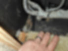
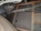
Installation wound up being much simpler than I thought (although it was complicated by a 40 minute round trip back home to get the correct step drill). I ended up using the dash air return cavity to drop onto a harness that ran under the floor in the general direction I wanted to go.


First, I installed the switch panel in the dash. Not seen is me easily sliding the cable over into the compartment adjacent to the chassis HVAC blower under the passenger side dash.
This is the only compartment (other than the electrical bay) that I had to open up to run the cable.
I drilled a 1" exit hole in the left inside corner of the blower compartment. I sealed this with a rubber grommet (Starlink wall pass through kit) and some spray sealant.
This brought the cable out right above the airbox and directly into an existing wiring loom running to where I needed it. Convenient! This is looking up and forward from behind the passenger front tire.
Then it was just a short drop to the electrical bay behind the passenger front tire. I elected to go through the plastic box part of the bay as I did not have visibility to come in behind the inverter, and did not want to remove it in order to safely drill the hole. This is looking up from behind the passenger front tire.
Since I had already connected the control cable on this end, all that remained was mounting the adapter plate and brackets, then connecting the motor and power lines to the controller. I verified directional operation of the jack motors first, and I did have to reverse the polarity from what was marked on the factory motor wires, when connecting them to the GAMA controller.
Next, I mounted the controller to the "roof" of the electrical bay. Note: I later replaced the screws, a.k.a hand shredders, holding the board to the mounting plate with machine screws and nylon lock nuts.
Since I had already run each motor a bit when testing polarity, I knew they worked, so I spent some time running them up and down a few times, before leaving them deployed and my rig leveled for the first time since I brought it home. Very happy moment!

Conclusion

I found very little information on getting my jacks properly working for less than full system replacement cost, so I wanted to put this out there to hopefully help someone else in the same boat, struggling with this terrible Atwood system, or one similar to it. There's a video or two out there on the GAMA controller, but nothing really detailed on how to deploy it as a jack controller, and nothing on a dash mount control pad replacement.


I originally planned to just use the pendant from GAMA and mount it to the dash somehow, but that would have been ugly, and the one-jack-at-a-time operation would have been painful. Once I saw how simple the wiring was for the pendant, I had to make something custom. If anyone else wants to try this on their rig, I am happy to share my STL design files, print settings, wiring schematics, etc. You could, of course, just use the GAMA controller with the RF remote, but I wanted to be able to level my rig from the captain's chair, and the heart wants what the heart wants.


It's worth mentioning that there are a couple of caveats with this design. The first is, all safety lockouts are gone. This could be a good thing to some, but it does mean, my pre-flight checklist will have to include checking the jacks every time, and making sure all the jacks are "off" when rolling, always. I may add a master lockout switch or relay, but I'll need to study up on the best way to do that. In their infinite wisdom, Tiffin chose to power the original system straight from battery, so with no lockouts, it will run if the coach has battery power. The second caveat is no auto-level, but I'll be adding a Levelmate Pro to cover that, and while it's not automatic, it suits my purposes just fine.


In the end, this was much easier than I anticipated. I have a lot of experience with these types of installs, having a background in design and manufacturing, and of course the 3D printer, so that helped. This is one of the more involved modifications I've made to our rig so far, but also by far the most rewarding. I'm very happy with the outcome, and I just hope the Atwood jacks last a while longer. Hopefully this helps or inspires someone else and feel free to ask questions. Also, sorry if I offended any Atwood fans! Parts list follows.


Parts List

4 x #8 x 1" stainless screws (to mount the control panel)

4 x #8 x 1" stainless machine screws, flat washers and nylon lock nuts (to attach the GAMA controller to the adapter plate)

Hatchbox Black PETG

Zip Ties


© 2024 Nathan Frith, all rights reserved


Comments


bottom of page